|
|
Post by scooter on Nov 1, 2019 1:42:18 GMT
I just acquired a nice monitor top and was told it ran but not ture . I pull the control box up and found 5 wires cut 3 taped together and two free. I really would like to restore this unit but need some help . I have already redone a nice flat top but was very lucky it ran. Not sure what the wires go to . Would greatly appreciate help. Thank you
|
|
|
|
Post by turbokinetic on Nov 1, 2019 2:23:39 GMT
I just acquired a nice monitor top and was told it ran but not ture . I pull the control box up and found 5 wires cut 3 taped together and two free. I really would like to restore this unit but need some help . I have already redone a nice flat top but was very lucky it ran. Not sure what the wires go to . Would greatly appreciate help. Thank you This is very concerning since they may have bypassed something important for the compressor motor protection.
Can you share some pictures? Also the DR manuals in the reference section could have a lot of info on how it's supposed to be wired.
|
|
|
|
Post by scooter on Nov 1, 2019 2:54:25 GMT
I can post photos but not sure how on this site
|
|
|
|
DR-1-b
Nov 1, 2019 3:52:32 GMT
Post by scooter on Nov 1, 2019 3:52:32 GMT
Unable upload pics anyway I take them always to big
|
|
btfarm
7 Cubic Foot

Posts: 103
|
Post by btfarm on Nov 1, 2019 13:06:10 GMT
Unable upload pics anyway I take them always to big Upload to Google drive and post the link here with permission for anyone with the link to view them. Alternatively, use a Flickr acct if you have one |
|
|
|
Post by scooter on Nov 2, 2019 4:10:50 GMT
Well I have done some research and the control is a cr 1050 e-1 . But all the pages I have looked at don't show me a wiring diagram to explain the five cut wires . I'm sorry I'm having a really hard time navigating this forum, I'm pretty computer savvy but really having hard time here sorry !!
|
|
|
|
Post by CCL2F2 on Nov 2, 2019 5:37:13 GMT
I would guess the three wires go to the motor and the two are for the sump heater.
|
|
|
|
Post by turbokinetic on Nov 2, 2019 14:00:16 GMT
Well I have done some research and the control is a cr 1050 e-1 . But all the pages I have looked at don't show me a wiring diagram to explain the five cut wires . I'm sorry I'm having a really hard time navigating this forum, I'm pretty computer savvy but really having hard time here sorry !! I found the 1050-E-1 control on page 40 of the manual (PDF page 44). As CCL2F2 said; you'll have two wires for the oil heater, and three for the compressor motor. The wiring diagram will make it easy to put things back the way they are supposed to go, once you are able to identify the wiring coming from the compressor. The "Figure 92 - Wiring of baseplate" is what you'll need for this. If the wiring colors are faded or darkened so that you can't identify them as shown in the manual, it's possible to make resistance measurements to figure it out. Un-tape and separate all the wiring. The first check should be for ground faults. Locate a clean, unpainted metal area on the machine (control base screw head?). Test for continuity between this ground point, and each of the wires from the machine. Any reading less than 1MΩ is worrisome. Anything below 100KΩ indicated a high leakage current path. If it's in the hundreds or tens of Ω range, it's a hard ground fault and no start attempts should be made.
With all the wiring disconnected; there will be two groups of wires with continuity to each other.
There will be one group of two wires with about 1000Ω measured between each other. These are the oil heater. It's very possible that these are open-circuit because the heater is bad after all the years. So if you find a pair of wires which have no continuity (or in the MΩ range) those would be the heater circuit (with bad heater needing to be replaced). There will be a second group of wires with much less resistance. These three will be the compressor motor leads. They should all have resistance in the 3 to 20Ω range, by estimate. I couldn't find a spec in the manual for the motor resistance; and also haven't had to make this measurement anytime recently. You need to measure the resistance all three ways. There will be three distinct, different resistance values. One of the three values will be the "sum" of the two other values and as such it will be much higher. When you find this "highest" resistance value, there will be one wire you're not testing. The wire not involved in the "highest" resistance reading will be the motor's "common" circuit. Mark it with "C." Now, measure between the newly marked Common circuit and the two others. There will be one circuit with less resistance. This is the Running circuit. The remaining wire will be the Starting circuit, as labelled below in GE's diagram. The reason I was hesitant to try to explain this is due to not having a resistance spec to give, not having done this test recently, and that the motor in these has an external starting resistor. Normally the winding its self has resistance for starting; but in the case of the DR it's external. So, the resistance difference between the two windings may be very small, or they could be backwards. Hopefully someone can confirm. I may have time to check one today, but not sure I will have the exact same model DR here as yours. The most important thing to do is, use a current meter when you try to start the machine. It should not draw more than 2 or 3 amps when running. If the wiring is reversed, and it somehow does start - the current demand will be excessive. You would need to power it off immediately to avoid damage. Hopefully we can come up with some resistance measurements later today. Sincerely, David 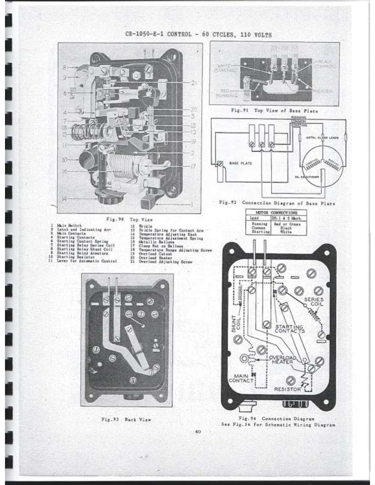 |
|
|
|
Post by turbokinetic on Nov 2, 2019 17:42:09 GMT
So, I took motor resistance measurements for two DR-type units today.
A DR-1 model, had 3.8Ω for the run-winding and 5.5Ω for the start.
A DR-D2 model, had 3Ω for run, and 4Ω for start.
So it looks like, even with the external resistor; the motor winding its self still has more resistance for the start winding.
Sincerely,
David
|
|
|
|
Post by scooter on Nov 2, 2019 19:04:18 GMT
Thank you so much for the help. I'll do some research, and post my results, thank again for your patience and knowledge
Scott
|
|
|
|
Post by turbokinetic on Nov 3, 2019 0:30:50 GMT
Thank you so much for the help. I'll do some research, and post my results, thank again for your patience and knowledge Scott You're welcome! I don't mind helping and do so when time allows. Looking forward to successful results! |
|
|
|
Post by scooter on Nov 3, 2019 3:04:49 GMT
Well I did some testing and the oil heater is bad. Still trying to figure out the compressor. Are heaters available?
|
|
|
|
Post by turbokinetic on Nov 3, 2019 3:06:29 GMT
Well I did some testing and the oil heater is bad. Still trying to figure out the compressor. Are heaters available? Heaters are available. We had a group-buy recently; but companies like Nordic Sensor can produce them one-off if necessary. |
|
|
|
Post by scooter on Nov 3, 2019 17:52:37 GMT
Ok did some testing and there is no continuity between cabnet top and motor wires. I take that as a good sign I checked motor wires and there is resistance on all three . Unfortunately I was studying the pdf and I realized I don't the base plate. Is there any way I can apply power to the motor to see if it will start with out damage?
|
|
|
|
Post by turbokinetic on Nov 3, 2019 19:03:56 GMT
Ok did some testing and there is no continuity between cabnet top and motor wires. I take that as a good sign I checked motor wires and there is resistance on all three . Unfortunately I was studying the pdf and I realized I don't the base plate. Is there any way I can apply power to the motor to see if it will start with out damage? That's good you don't have shorts to ground, and also DO have continuity on the motor. What sort of resistance do you have on the compressor motor? Yes, you can definitely run the compressor without the control base. It would most likely be possible to hard-wire the control to the wiring from the cabinet; however you may be able to get a control baseplate. To be sure we are on the same page, could you post a picture of the control and the cabinet top where the wiring comes out? You will need a starting resistor (or capacitor) in the circuit for any start attempts. A good choice would be a Supco RCO810 device, since this has a capacitor, motor protector, and start relay in one. These are readily available from any HVAC supply house. While that may not help today (Sunday) you might be able to get that tomorrow. With the RCO810 you will be able to run the compressor, safely, without the original control connected at all. You'll need to know which wires are what on the compressor motor. If the colors are gone after all the years, your resistance measurements will help to figure it out. |
|


