|
|
Post by coldspaces on Aug 14, 2013 4:53:20 GMT
When I brought my 38 Flat Top home the start relay/overload was about to go out and after just a few days use it did. I tried using a small PTC relay mounted inside the original housing so that the original sound of the relay would still be heard. There just wasn't any current going through the old burnt contacts anymore. It worked but I did not like the way it kept the start winding engaged longer than the original relay. It also did seem to run too hot and warp its plastic housing. Not sure if that was caused by mounting it vertical instead of its normal horizontal position or if the draw through the original relay coil was affecting how hot the PTC material got. Anyway when I was rewiring the machine I broke the housing of the overload and rendered it useless. This caused me to just replace the relay and overload inside of the original Type N housing. The original relay was the type N relay/overload and it was only used on the early 1938 flat tops. After the 1st 1/4 of production it was replaced by the type R relay/overload. The type R relay/overload was similar with a change made to make it work better for 50 cycle operation. My original N relay part # was M1A162 Specs are 60 cycle, 1/8 hp, pick up current amps 6.0, minimum drop out current amps 5.5, overload rating 3.2 amp.(trip point not RLA rating )  I replaced it with this Marrs relay and a modern overload.  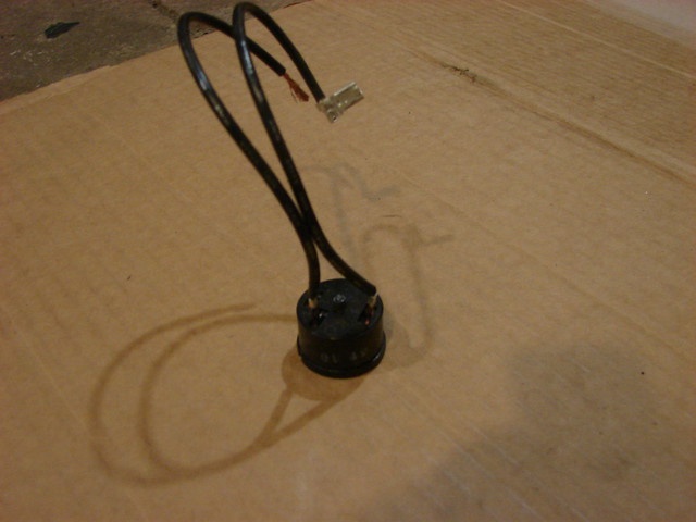 Relay specs - 1/8 Hp, Max pick up amps 5.2, Minimum drop out amps 4.4. This was the closest I was able to find in the Mars current relay line. It has worked great when I have run it and even still has some sound of a mechanical relay. After the box cools off and the system stabilizes it starts very fast and quite. I personally prefer it over the PTC relay. Overload I used is for a Tecumseh compressor model AE1336A, 375 btu, RLA 1.7, Not sure what the LRA rating is. View of old the contacts.  Plenty of burnt junk inside of the old housing.  In order to fit the new relay and overload I gutted a lot of the old relay components. 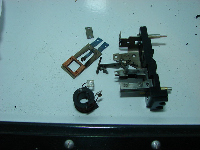 The relay was a tight fit and and I had to trim the plastic on the sides to make it fit.  Also had to rebend the spade terminals more straight up to make it fit. 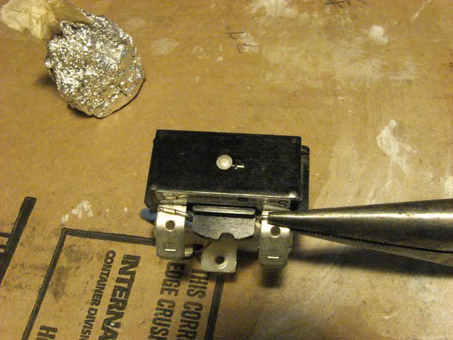 I did not have an easy way to hook to the pin connections so I stipped back some 14 ga stranded wire and directly soldered it in without any trouble at all.  The relay was placed so that up was the same as the original housing was labeled and wire tied on. The overload I did not get a pic of but it is in there.  When done the only real clue I worked on it is the ground wire I added.  I did have a challenge getting all the wiring to fit inside the housing and had to solder and shrink wrap connections to make it fit. It would probably be better to remove the complete insides of the old relay to have more room inside of the old housing to work. The new relay and overload could be secured in the old housing with RTV silicone if needed. From what I have seen most the old 1/8 Hp compressors draw about the same watts and I feel confident that this relay/overload combination will work on most all of them. |
|
|
|
Post by ChrisJ on Aug 14, 2013 13:09:22 GMT
I'm curious why the preference of the mechanical over the PTC relay?
|
|
|
|
Post by coldspaces on Aug 14, 2013 15:19:04 GMT
I'm curious why the preference of the mechanical over the PTC relay? Just the fact that it does not have to cool down before it will power up the start winding again and it keeps the start winding engaged for less time. Not that the PTC keeps it on to long, just longer. Also can still hear a mechanical relay noise some. From what I am seeing with the other old frigs I have with relays like the GE Hot Wire and replacements for them (I have NOS SYT relays made by SUPCO) they keep the start winding in the circuit just as long or longer than the PTC relays do. As long as the PTC relay is used with the proper size overload it is fine. I just prefer the mechanical relay. |
|
|
|
Post by cablehack on Aug 15, 2013 0:00:19 GMT
I must admit to a slight preference to the mechanical relay for the reasons Coldspaces has outlined above.
In my life as a TV technician, I had a lot to do with PTC thermistors as they're also used to power up the degaussing coils around the picture tube, for about a second, when the set is first switched on. Just because they are called "solid state", doesn't mean they are completely reliable because of lack of moving parts. On the contrary, I have seen examples both short circuit, and open circuit. In fact, one mode of failure is the thermistor can actually break apart. Then no current flows.
Now, don't get the impression I'm saying they're an unreliable component. They're not - but it shouldn't be assumed they will work forever no matter what, and will automatically outlive a mechanical relay.
One of my concerns is that for a PTC thermistor to work is that it relies on heat to make the resistance go high, and thus the current in the start winding (or degausssing coil in a TV) to rapidly fall. To keep the PTC warm means that in the case of a fridge motor, some current always has to flow through the start winding. A lot less than the initial start up current of course, but some current nonetheless.
There is also the issue of the time taken for the PTC to warm up and drop the current. This is longer than a mechanical relay takes to do its job. It may or may not be significant, but exposing the start winding to current longer then necessary is certainly not going to improve its longevity.
Next, is the thermal delay characteristic. If the power to the motor should be interrupted just after it has started, and the PTC is still hot, it will be unable to start again. This will cause higher than normal current to flow in the run winding. Hopefully, there will be over current protection in the circuit.
The question of originality is really more an emotive thing. One could argue that once a vintage piece of technology is "updated", "modernised", "improved", or whatever you want to call it, there isn't really much of the original left, in appearance, or operation.
As far as start relays go, I can see that for a non technical person who just wants to get the fridge running, with good reliability, the PTC has a lot going for it.
|
|
|
|
Post by ChrisJ on Aug 15, 2013 0:37:39 GMT
I feel a mechanical relay with contacts that can fail would be less reliable.
Now, my main reason for installing an RO81 was for overload protection. If a modern mechanical relay has this as well then I don't see a problem with that either.
|
|
|
|
Post by cablehack on Aug 15, 2013 1:15:27 GMT
I was thinking more along the lines of monitor top owner that once asked how to replace the mains cord on a CK, in terms of being non technical.
For overload protection, you could use the relevant PTC of the R081 in series with the mains supply, allowing the relay and compressor wiring to remain original. You've just given me an idea for a useful accessory that any fridge, vintage or otherwise, could be plugged into....a short extension cord cut in half with a box in the middle containing an R081 overload PTC.
Speaking of overload protection, I've been wondering if the CK3 that was on ebay which had a modern control fitted, has any overload protection. The solder pot overload device won't be present if they've taken the original control out of circuit.
|
|
|
|
Post by coldspaces on Aug 15, 2013 4:09:29 GMT
The question of originality is really more an emotive thing. One could argue that once a vintage piece of technology is "updated", "modernised", "improved", or whatever you want to call it, there isn't really much of the original left, in appearance, or operation. In my case the old relay was shot so some kind of modernization had to happen. Did not think there was much chance of finding NOS parts so I chose to find a replacement I could hide in the original housing and still have a mechanical relay. With machine like ours being 75 and more years old things like start relays and cold controls are gonna go out and have to be repaired or replaced with something. I like to find ways to hide that the work has been done to at least keep it looking original as possible. |
|
|
|
Post by coldspaces on Aug 15, 2013 4:13:00 GMT
I was thinking more along the lines of monitor top owner that once asked how to replace the mains cord on a CK, in terms of being non technical. For overload protection, you could use the relevant PTC of the R081 in series with the mains supply, allowing the relay and compressor wiring to remain original. You've just given me an idea for a useful accessory that any fridge, vintage or otherwise, could be plugged into....a short extension cord cut in half with a box in the middle containing an R081 overload PTC. Speaking of overload protection, I've been wondering if the CK3 that was on ebay which had a modern control fitted, has any overload protection. The solder pot overload device won't be present if they've taken the original control out of circuit. 1/8 HP overload like used could be placed in the box in the middle of the cord if you don't need the relay. |
|
Grigg
5 Cubic Foot
 
Posts: 95
|
Post by Grigg on Aug 15, 2013 15:00:21 GMT
coldspaces, if this is a good conversion for the relays on old 1/8 hp compressors a shopping list and diagram would be handy. I've done some digging but not sure what it all means, which part numbers we should be looking for? From the picture looks like you used Mars relay 27002. Which is supposed to be interchangeable with Tecumseh 82611 and GE 3ARR12 PAC310A. Here's some info , page C-33. max pickup 5.2 and min dropout 4.4 Do you know if those alternate part numbers are also suitable or better to stick with the Mars part as you used? Looking for a part number on the overload relay you used that was intended for a Tecumseh compressor model AE1336A it looks like that compressor was superseded by AEA1336AXA The literature for the newer version has the same Rated Load Amps (RLA 60 Hz) of 1.7 It also does list the Locked Rotor Amps (LRA) at 14.6. It shows two different overload #s used with that newer compressor depending on the bill of material. One is Overload #: 83613 and Replacement Overload Kit #: K90-01 Or Overload #: 83649 and Replacement Overload Kit #: K90-01 I find it a little odd or confusing that they specify the same kit to be used but appears that otherwise there is a slight difference in the overload relay? If you cross reference the two overload numbers they are still different. I couldn't find any spec sheets or details on any of the 4 numbers. Tecumseh to Mars 83613 -> 35005 83649 -> 35004 |
|
|
|
Post by coldspaces on Aug 15, 2013 18:58:54 GMT
Looks like you may have just done the list for me LOL. The overload was NOS I already had for years, klixon # MRK 40 HX I looked it up backwards in my tecumseh cross and found it replaced a P83504. Then found it was for the old AE1336A compressor at 1.7 amp. From what I have read the N relay tripped at 3.2 if I understand it right, The Type R relay on my GE spacemaker from aprox 40s also says 3.2 amp. The type R was the replacement for the N so that makes sense. Not sure about my 32, DR manual refers to adjusting the overload and then testing how many seconds it takes to trip not what amps it trips at. All 9 of my old frigs are 1/8 hp and seem to draw about the same 160 watts after the box is cooled out. Check the link below and you will notice that Mars sells these by the hp, not just by exact cross reference. Looks to me like they expect the # 27002 to work on most 1/8 hp compressors. I think this relay would work on all our 1/8 hp compressors unless the CA compressors use less amps. controlscentral.com/Portals/0/data_sheets/C-33_MARS_SERIES270.pdfAlso in all my recent reading somewhere I read how to determine what current relay to choose. Can't find it again to link it but am pretty sure it was on a manufacturer of compressors or current relays web site. First disconnect the start winding so only the run winding gets power. Place an amp meter on the run wire. Plug in compressor briefly and measure the draw of the run winding. Say it is 8 amps. Now choose a relay with a pick up current rating below 8 amps. If you choose one at or above the 8 amps it will never pull in the contacts and power up the start winding. Next read model tag and find the RLA of the compressor. Your relay must drop out at a current higher than the RLA or the start winding will stay engaged and trip the overload. If you don't know the rated RLA you can reconnect the start winding , run it and measure it. Of course it may not be at full load so some compensation will be needed to be sure your drop out amps are not to low. In the case of my flat top I knew the specs of the old relay thanks to the info cablehack had posted so I chose the closest match. I believe the run winding drew 8 amps when I checked and the tag says 2.2-4.3 max amps. Don't see how it would ever be 4.3 like it says though. Anyway the mars relay # 27002 picks up at 5.2 and drops out at 4.4 which would fall within these specs. PS many times the only difference in the overloads is whether the compressor has a fan cooled condenser or static cooled. |
|
|
|
Post by coldspaces on Aug 18, 2013 21:11:09 GMT
Here is what I have come up with for the wiring.
Original wiring of my N relay.  Mars relay instructions. drive.google.com/open?id=0B6Wm1OROcVR-UWYyQVBWWUd2QW8Overload  Relay mounting kit for various older frigs. Mars # 93104 QC-11 Here is everything that commes in the kit.drive.google.com/open?id=0B6Wm1OROcVR-Uy1PM3NVTXd3NGMHere you can see I soldered the run winding directly into the relay. Red = run lead.  White wire = start lead Blue tagged wire= Neutral lead. Since I was not using a start capacitor the blue jumper was left in place between the side terminal #1 and top terminal #2. I did not have much room over the relay so I hooked the neutral lead on the side at #1.  |
|
|
|
Post by cablehack on Aug 18, 2013 23:51:41 GMT
Thanks for this information, and the modern part numbers. While there is a lot of room under the CF to install whatever you liked, in the case of the CK where it has to be squeezed in between the fins, having a retrofit that fits in the original enclosure makes things much easier. And it looks right from an aesthetic point of view.
|
|
|
|
Post by coldspaces on Aug 19, 2013 0:27:42 GMT
Next time I think I would gut the inside completely, attach wire pigtails to relay and overload, glue them into the housing with RTV, let dry then hook up the rest of the wiring. Would be a lot more room for the wires then. Just don't get RTV into the overload.
|
|
|
|
Post by coldspaces on Aug 20, 2013 2:37:05 GMT
Realized tonight that I had mixed up the type E relay and type R. I have edited the thread to show the Type R was the replacement for the Type N.
|
|
|
|
Post by coldspaces on Aug 20, 2013 4:25:27 GMT
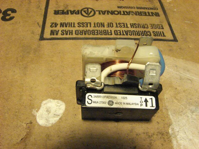
Well now I am going to see if I can fit the Mars 27002 relay and an overload inside of the housing of a type R relay. Of course since these old relays were also the central point for the wiring I still need to be able to get a lot of wires in it also. And I am even entertaining trying to add ground wiring. Don't think I can make it all fit but we will see. Here is a type R relay/overload from a GE Spacemaker frig from the late 40s. Should be the same housing shown for the CF machine. Also I believe it may have been used on the monitor tops as a replacement for the type E relay.( correct me if that is wrong) There is that 1/8 hp 3.2 amp rating again.  Heres whats is going in.  Relay is not a good fit out of the box at all.  Stated by trimming extra from the one side. 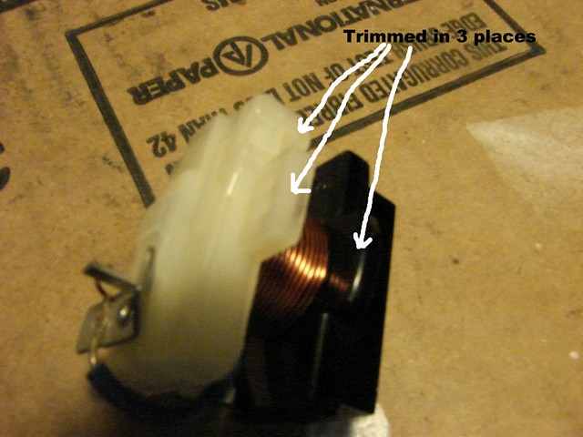 Be careful working near the relay coil, took my time and did not force the dremel and no coil damage was done.   End of relay was still just a little too wide. I had to trim more plastic off including the part that holds the plastic top to the piece under it. This needs to stay in place to keep the run and start terminals away from each other so I will glue the plastic in place with the RTV that will hold the relay in the housing. 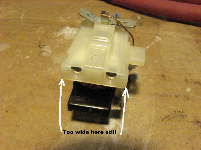  Bent the spade for the start winding back out of the way. I will not use this spade connection as I will be soldering in pigtails for the run and start leads. 
Still would not fit back into the housing enough so I trimmed on the other side.
   Hopefully just enough room for the pigtails to get out from behind it.  Gonna place the overload in the top area like this. Relay does not sit totally plumb in the housing but it should not be enough to matter. 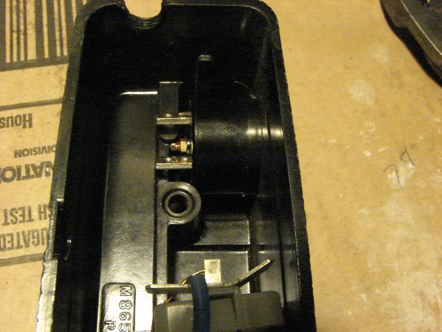  Next I stripped the ends of some wires and soldered them into the pin connector on the relay. Red = run (labeled M on the relay) White = start 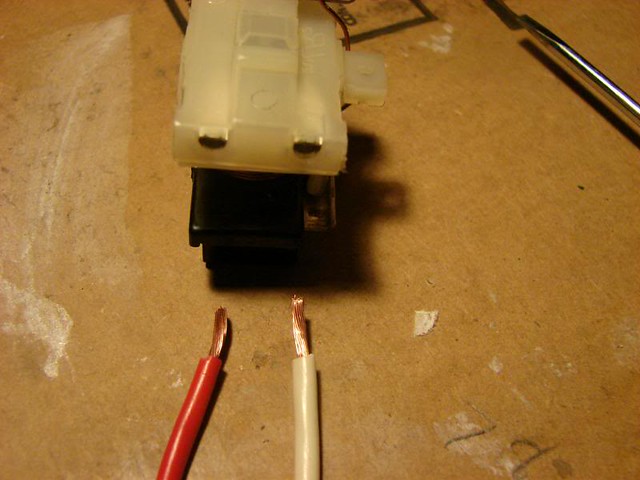 Before soldering them in I bent them 90 degrees straight up.  Soldered in, melts a little plastic but as long as the pin connector gets hot enough for the solder to take thats ok.  Applied some RTV to the top sides and bottom of the relay. Sorry for the poor pics not sure what I caused the camera to do.   Here it is installed in the housing.  Guess I won't be hooking to spade connector # 1 either so I bent it up to make room for wires. Now gotta let the RTV dry.  Here is the new wiring I made up for the relay. Type SEOOW 16/4 & 16/3 was used. Due to the fact the new wire is bigger diameter I removed the jacket and filler at the ends,then put a double layer of shrink tube on the ends. This allowed the wires to fit through the factory openings on the relay housing. Could also use a dremel and make the openings larger. Top wire goes from relay up to the inside of the box. Red wire with loop is power returning from the cold control to feed the overload. Middle wire is compressor lead. Black wire with loop is common lead from the overload. Bottom wire is the power cord.  So now I have decided to solder the neutral wires directly to the spade connector. Would have been better if this was done before the relay was in the housing but I managed to get it.  Tying the grounds together. 
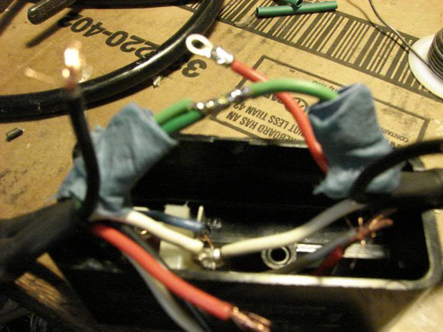 The main power up to the box, start and run leads were all soldered together at the ends and double shrink tubed.  Start and run leads tucked nicely down inside of the housing. 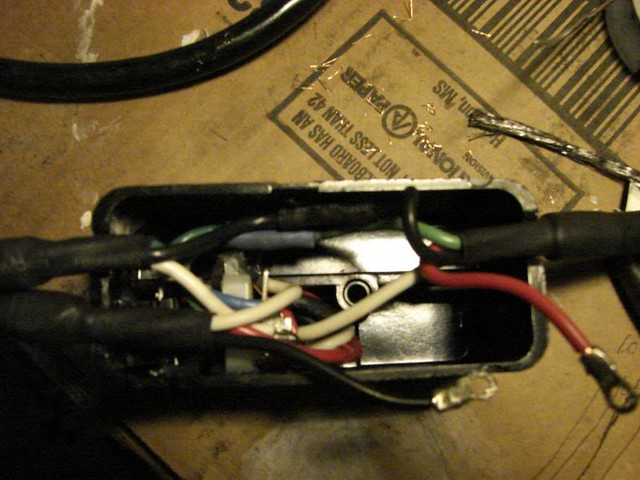 Overload ready to go in.  DSC08082_zps23bc3a78 DSC08082_zps23bc3a78 by Gill Colwell Sr., on Flickr Fits in pretty good. 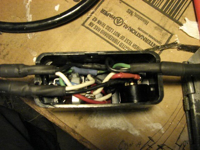 Here I have a screwdriver blade wedging the overload against the side of the housing tight. Then applied some RTV to hold it in place.  Next I will cut an insulator sheet to fit across the opening of the housing. That way Next I will cut an insulator sheet to fit across the opening of the housing. That way nothing should be able to touch the metal mounting plate latter. |
|


